

How to Choose the Right PV Wire for Global Solar Projects?
Choosing the right pv wire can influence a solar project’s safety, service life, and long-term performance. A cable installed on a dry rooftop may face very different conditions from one placed beside a humid coastline. Strong ultraviolet exposure, high temperatures, water, abrasion, and repeated thermal movement can gradually weaken unsuitable materials.
Experienced project teams usually examine more than conductor size. They check insulation quality, voltage rating, temperature range, flexibility, flame behavior, and resistance to sunlight and moisture. The connector system also matters. A well-rated cable can still create risk if it does not fit the selected connectors correctly. Small details matter.
Global projects require careful attention to regional requirements and recognized standards. IEC 62930, EN 50618, and UL 4703 are commonly referenced in different markets, but they should not be treated as interchangeable approvals. Engineers and procurement teams should verify the current requirements for the installation location. Certification records, factory quality controls, test reports, and traceability deserve practical review.
A reliable selection process also considers installation realities. Will workers pull the cable across sharp metal edges? Will the array experience strong wind, snow, or frequent maintenance? A cable that performs well in a laboratory may be less suitable after careless routing or excessive bending. This is where project experience becomes valuable, although experience alone is not enough. Conditions change, and assumptions can fail. Good decisions combine technical data, site evidence, qualified advice, and honest review of remaining uncertainties.
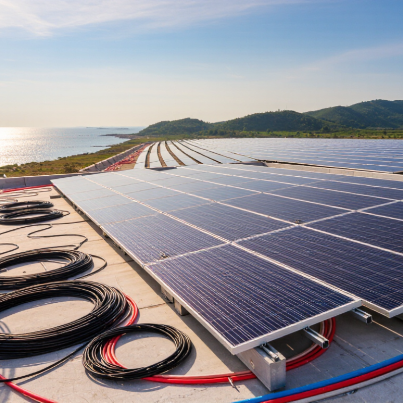
Table of Contents
[Hide]
PV Wire Basics and Its Role in Solar Power Systems
How to Choose the Right PV Wire for Global Solar Projects?
PV Wire Basics and Its Role in Solar Power Systems
PV wire carries direct current from solar modules to inverters, batteries, and other equipment. It operates under sunlight, heat, moisture, and mechanical stress. Its insulation must resist ultraviolet exposure and remain flexible during installation. The correct wire also needs suitable voltage, current, temperature, and wet-location ratings. A cable that looks strong may still fail inside a hot conduit. That detail is easy to miss.
Cable sizing depends on current, distance, installation method, and allowed voltage drop. Larger conductors can reduce energy loss across long rooftop or ground-mounted arrays. However, oversized wire may raise costs and complicate termination. Global projects require careful review of local electrical codes and recognized testing standards. Requirements can vary between regions. Connector compatibility matters too. A mismatch can create heat at the joint, even when the cable itself is properly rated. Qualified electrical professionals should verify calculations and installation practices.
Tips: Check the wire marking before installation. Confirm its voltage, temperature, and environmental ratings. Keep cables away from sharp metal edges and standing water. Use secure clips, not tight bends. Leave no loose loops on the roof. Field inspections often find avoidable damage near connectors. I have also seen project teams trust a familiar specification without checking local rules. That shortcut deserves reconsideration. Reliable selection combines documented test results, practical routing plans, and regular inspection records.
How to Choose the Right PV Wire for Global Solar Projects? - PV Wire Basics and Its Role in Solar Power Systems
Technical selection guide for photovoltaic DC wiring in rooftop, utility-scale, floating, and high-voltage solar installations
| Selection Dimension | What to Verify | Typical Technical Data or Criteria | Role in the Solar Power System | Project Checkpoint |
|---|---|---|---|---|
| Application and Circuit Location | Identify whether the cable will be used in module leads, string circuits, combiner-box wiring, tracker systems, or underground DC routes. | Module interconnection String wiring Combiner connection Buried route | Different locations experience different levels of movement, sunlight, moisture, mechanical stress, and installation exposure. | Map the complete DC route before selecting the cable construction. |
| Voltage Rating | Select a cable voltage rating equal to or higher than the maximum DC system voltage, including applicable design margins. | Common PV system classes include 1,000 V DC and 1,500 V DC. The cable rating must also match the connector and other DC components. | A suitable voltage rating helps prevent insulation breakdown, arcing, and premature system failure. | Confirm the inverter, module, connector, fuse, and cable voltage ratings as one coordinated system. |
| Applicable Standards | Use the standard required by the installation country, authority having jurisdiction, and project specification. | IEC 62930 and EN 50618 are widely used for photovoltaic cables in international and European projects. UL 4703 is commonly referenced for photovoltaic wire in North American installations. | Standards define requirements for construction, electrical performance, flame behavior, insulation, environmental resistance, and testing. | Check the latest national adoption, certification scope, and acceptance requirements. |
| Conductor Material | Verify conductor material, flexibility, stranding, and compatibility with terminals and connectors. | Stranded copper is widely used; tinned copper is common where improved corrosion resistance is needed. Aluminum conductors may require specially approved terminations and installation methods. | The conductor carries DC power and influences voltage drop, heating, flexibility, and long-term connection reliability. | Confirm conductor class, plating, termination method, and compatibility with the selected connector. |
| Cross-Sectional Area | Size the conductor using ampacity, allowable temperature, installation method, grouping, ambient conditions, and voltage-drop limits. | Common PV cable sizes include 4 mm², 6 mm², and 10 mm², but the correct size must be calculated for the actual project. | A correctly sized conductor limits resistive losses, excessive heating, and reduced energy yield. | Apply local electrical rules and verify both thermal capacity and voltage drop. |
| Current-Carrying Capacity | Use the cable ampacity after applying correction factors for ambient temperature, sunlight, conduit, tray, burial, and bundled circuits. | PV string current is normally based on module short-circuit current with the safety factors required by the applicable code. Do not use nominal operating current alone. | Proper ampacity prevents overheating under continuous daytime operation and abnormal operating conditions. | Use the worst-case design temperature and installation arrangement. |
| Insulation and Sheath | Choose insulation and jacket materials designed for long-term outdoor DC photovoltaic service. | Cross-linked polyolefin compounds are commonly used because they provide strong resistance to heat, sunlight, moisture, and aging. | The insulation maintains electrical separation between the conductor, equipment, and surrounding structure throughout the cable life. | Verify material classification, thickness, flexibility, and compatibility with the installation environment. |
| Temperature Performance | Check the cable's minimum installation temperature, maximum continuous operating temperature, and short-circuit temperature limits. | Many PV cables are designed for outdoor operation around -40°C to +90°C, with higher short-duration conductor limits specified by the applicable standard and construction. | Temperature capability affects ampacity, insulation life, routing method, and performance in hot climates. | Use the manufacturer's certified temperature ratings rather than relying only on ambient-air temperature. |
| UV and Weather Resistance | Confirm resistance to ultraviolet radiation, rain, humidity, ozone, and repeated outdoor exposure. | For exposed routing, use cable specifically tested and marked for sunlight resistance and photovoltaic service. | UV and weather resistance reduce cracking, embrittlement, water ingress, and insulation degradation. | Do not substitute general-purpose building wire unless it is approved for the intended exposed application. |
| Moisture and Water Resistance | Assess whether the cable will be exposed to rain, condensation, standing water, wet conduit, or periodic immersion. | Outdoor PV wiring should have a wet-location rating appropriate to the governing code. Floating solar projects require additional consideration of splash, humidity, and water exposure. | Moisture-resistant insulation helps prevent leakage current, corrosion, insulation failure, and ground faults. | Review wet-location and immersion requirements for the exact route and site conditions. |
| Mechanical Flexibility | Match cable flexibility to fixed installation, tracker movement, module articulation, and repeated bending. | Use flexible stranded construction for normal PV routing. Tracker applications may require cables qualified for repeated movement and a defined bending radius. | Correct flexibility reduces conductor fatigue, jacket damage, connector stress, and intermittent faults. | Follow minimum static and dynamic bend-radius requirements during installation and operation. |
| Connector Compatibility | Ensure the cable diameter, conductor size, insulation dimensions, crimp range, and connector approval are compatible. | Use connectors and cable components that are approved as a matching system. Avoid mixing mating connectors from different systems unless specifically permitted and tested. | Reliable connections reduce contact resistance, hot spots, arcing, and water ingress. | Verify crimp tooling, contact material, insertion depth, locking, and pull-out performance. |
| Flame and Fire Performance | Check flame-retardant, smoke, and fire-performance requirements for the project location and building type. | Requirements vary between rooftop, building-integrated, utility-scale, and underground installations. Local fire codes may impose additional routing or material requirements. | Fire-performance characteristics help limit flame spread and support safe maintenance and emergency response. | Coordinate cable selection with the project fire strategy and authority requirements. |
| Voltage Drop and Energy Yield | Calculate voltage drop over the complete positive and negative DC circuit length. | A practical design target is often approximately 1% to 3% for a DC circuit, subject to the project energy model and local design rules. | Lower resistance improves energy delivery and reduces electrical losses, especially on long string and central-inverter routes. | Calculate using actual one-way route length, operating current, conductor resistance, and temperature. |
| Installation Method | Define whether the cable is clipped, laid in tray, installed in conduit, buried, attached to a tracker, or routed through a module frame. | Installation method determines ampacity correction, protection from abrasion, support spacing, bend radius, and exposure to water or heat. | Correct installation protects the cable and ensures that its certified electrical ratings remain valid. | Design the cable route and support system before finalizing the cross-section. |
| Environmental Conditions | Evaluate altitude, desert dust, coastal salt, tropical humidity, snow, ice, chemicals, rodents, and agricultural exposure. | Coastal and humid sites may require enhanced corrosion protection; desert sites require high UV and temperature resistance; high-altitude sites require review of insulation coordination. | Environmental matching improves service life and reduces maintenance, faults, and unplanned downtime. | Use site-specific environmental data rather than generic climate assumptions. |
| Polarity Identification | Use durable and clearly identifiable positive and negative conductors throughout the DC circuit. | Common identification methods include contrasting insulation colors, permanent markings, and clear circuit labels. Follow the local wiring code. | Correct identification reduces reverse-polarity connections and speeds up commissioning and maintenance. | Confirm color conventions and labeling rules before installation. |
| Traceability and Documentation | Obtain datasheets, test reports, markings, certificates, batch information, and installation instructions. | Documentation should state voltage rating, temperature range, conductor size, standard reference, environmental ratings, and allowable installation conditions. | Traceable documentation supports quality control, inspection, warranty evaluation, and regulatory acceptance. | Include cable records in the project quality plan and as-built documentation. |
| Inspection and Maintenance | Plan visual inspection, connector checks, thermographic testing, insulation testing, and fault-location procedures. | Inspect for discoloration, cracking, loose connectors, unsupported cable loops, abrasion, water ingress, and signs of overheating. | Early detection helps prevent ground faults, arc faults, fires, and production losses. | Define inspection intervals according to site conditions, system size, and operating experience. |
Engineering note: Cable selection must be validated against the latest local electrical code, project specifications, certified product documentation, connector requirements, and site-specific calculations. Typical values shown in this table are guidance ranges and are not a substitute for a project design review.
Related Posts
-
How to Choose the Right Solar Wire for Your Project?
-
2026 Best Solar PV Wire Options for Optimal Performance?
-
2026 Top Trends in Solar PV Wire Technology and Applications?
-
2026 Top Trends in PV Wire Applications and Innovations
-
How to Choose the Right PV Wire for Your Solar Projects?
-
Top 10 Best Solar Wire Options for Global Buyers?