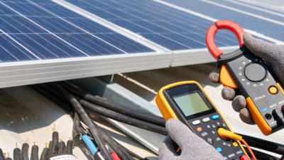
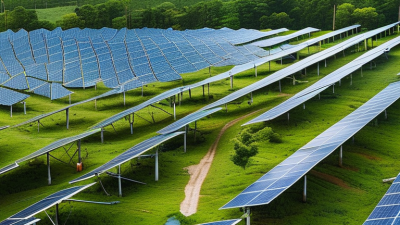
Solar power is expanding quickly, but every watt still travels through physical conductors. The IEA PVPS Trends 2024 report records about 1,419 GW of global photovoltaic capacity by the end of 2023. IRENA also reports roughly 346 GW of new solar capacity added during 2023. Behind those impressive figures are thousands of meters of cable, exposed to sunlight, rain, heat, and mechanical stress.
This is where solar cable becomes more than ordinary electrical wiring. It must withstand ultraviolet radiation, ozone, temperature swings, moisture, and repeated movement near modules and inverters. TÜV Rheinland photovoltaic reliability expert Dr. Peter Hacke has emphasized, “Reliability is not just a laboratory result; it is a field-performance result.” That principle matters when a cable lies beneath a hot panel roof for twenty-five years.
A correctly selected solar cable uses suitable insulation, conductor sizing, and certified connectors. IEC 62930 and EN 50618 provide important reference points for photovoltaic cables, although compliance alone does not guarantee perfect installation. Cable routing, bending radius, connector compatibility, and water protection still depend on human workmanship.
Small details matter. A poorly supported cable can rub against a sharp frame edge. A loose connector can heat quietly before failure becomes visible. Solar cables are not always the most exciting component. They are easy to overlook.
That may be the weakness in many projects. Designers often focus on module efficiency and inverter performance, while cable quality receives less attention. Choosing the right solar cable protects energy yield, maintenance budgets, and long-term system reliability.
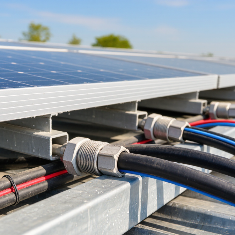
Solar cable is a purpose-built electrical cable for photovoltaic systems. It carries direct current from solar modules to inverters, batteries, and combiner boxes. Unlike ordinary building wire, it usually has double insulation and strong resistance to ultraviolet light, ozone, moisture, and temperature changes. Common photovoltaic cable designs follow IEC 62930 or EN 50618 requirements.
A cable sits under real stress. It may rest on a hot roof, touch a metal rail, or face years of rain and sunlight. Its flexible copper conductor reduces installation strain, while the outer jacket helps prevent cracking and abrasion. Correct polarity and secure connectors are equally important. Small installation errors can create heat at connection points.
The scale is significant. The IEA PVPS Trends in Photovoltaic Applications 2024 report states that global photovoltaic capacity exceeded 1.6 terawatts by the end of 2023. More systems mean more cable exposed to demanding outdoor conditions. The U.S. National Renewable Energy Laboratory has also reported that cable routing, connectors, and other balance-of-system parts deserve careful inspection during long-term operation. A cable may look perfect and still hide damage. That assumption needs questioning. Undersized conductors, excessive bending, or loose connections can increase voltage loss and fire risk. Selecting the right solar cable requires checking current, voltage, temperature, installation distance, and applicable standards—not only its appearance.
Solar power systems operate outdoors for decades, unlike most indoor electrical installations. The difference begins with the cable.
Standard electrical cables often use insulation designed for protected buildings. Solar cables use materials and construction suited to sunlight, heat, moisture, ozone, and repeated temperature changes. Many include double insulation and fine-stranded copper conductors for easier routing around modules. Their jackets must resist cracking when exposed to ultraviolet radiation. Standards such as IEC 62930 and EN 50618 define important requirements for photovoltaic cables, including voltage ratings, flame behavior, and environmental durability.
The scale of the industry makes cable reliability more important. The IEA PVPS Trends 2024 report recorded more than 1.6 terawatts of global photovoltaic capacity by the end of 2023. A small cable weakness can therefore affect a large energy asset. NREL’s Photovoltaic Degradation Rates report found a median module degradation rate near 0.5% per year. Cable damage can create additional losses much earlier, especially through loose connections, water entry, or insulation failure.
A common mistake is choosing cable only by conductor size. It can fit electrically, yet fail mechanically. Installers should check temperature ratings, outdoor certification, bending limits, connector compatibility, and installation conditions. Cable routing also matters. A cable dragging across a sharp metal edge may deteriorate faster than laboratory testing suggests. The comparison is not perfect, either. Certified solar cable can still fail after poor installation, excessive tension, or unmanaged heat. Small details matter.
Why Choose Solar Cable for Solar Power Systems?
Key Features That Support Safe Solar Power Transmission
Solar cables are built for demanding outdoor conditions. Their insulation resists sunlight, ozone, moisture, and repeated temperature changes. This matters on rooftops, where a cable may face intense heat at noon and cold air after sunset. Cross-linked insulation also improves durability and reduces cracking during long-term exposure.
Safe transmission depends on more than insulation. The cable must match the system’s direct-current voltage, expected current, and installation temperature. A suitable conductor limits voltage loss and unwanted heating. Flexible construction helps installers route cables around rails and junction boxes without sharp stress. Flame-resistant and low-smoke materials can provide added protection, depending on local requirements. However, a cable can look excellent and still fail when its size or connector is poorly matched.
Tips: Check the cable’s voltage and temperature ratings before installation. Keep positive and negative conductors properly separated. Protect cables from sharp metal edges and standing water. Respect the stated bending radius. Inspect exposed sections for cuts, discoloration, or loose connections. Small oversights matter. In practice, rushed routing is one detail people may underestimate. Reliable performance comes from the complete installation, not from the cable alone.
Why Choose Solar Cable for Solar Power Systems?
How to Choose the Right Solar Cable for a PV System
Choosing solar cable starts with the installation environment, not the price. PV cables must handle sunlight, rain, heat, cold, and repeated temperature changes. Their insulation should resist ultraviolet exposure and mechanical wear. I have seen ordinary electrical cable become brittle after years on an exposed rooftop. That failure can create unsafe faults and costly repairs.
Match the cable’s cross-sectional area to the system’s current, voltage, route length, and installation method. Longer runs may need a larger conductor to reduce voltage drop. Check the cable’s temperature rating, insulation class, flexibility, and compatibility with the connectors. Use cables tested against recognized photovoltaic standards. The cable should also suit rooftop gaps, conduit sections, and areas near sharp metal edges. My early mistake was checking only current capacity. Heat buildup and cable routing mattered more than expected. A neat calculation is not enough.
Tips: Measure the actual route before ordering. Leave enough length for clean bends, but avoid loose loops. Inspect insulation for cuts or flattening. Keep positive and negative conductors secure and clearly identified. Select matching connectors from the same approved system. When conditions are unusual, ask a qualified installer to verify the design. Small shortcuts can become expensive.
This chart shows the calculated voltage drop for different copper conductor sizes in a 60 m total circuit length carrying 10 A at 600 V DC. The calculation uses copper resistivity of approximately 0.0175 Ω·mm²/m at 20°C. A larger conductor has lower resistance and reduces power loss, while the final cable choice must also consider current capacity, operating temperature, UV resistance, mechanical protection, and applicable PV installation standards.
Solar cable is built for the demanding conditions found in photovoltaic power systems. Its insulation must resist sunlight, moisture, temperature changes, and mechanical stress. In a photovoltaic system, cable choice affects safety, energy yield, and service life. Installation conditions matter just as much. A high-quality cable can still perform poorly when routed carelessly.
Cable size should match the system’s current, distance, and allowable voltage drop. Long cable runs may require larger conductors to reduce energy loss. Installers should also check the cable’s temperature rating. Dark roofs can become extremely hot under direct sunlight. Cables placed near metal surfaces may need additional spacing or protection. Never force a cable around a sharp corner. That mistake can damage insulation without leaving an obvious mark.
Routing deserves close attention. Keep cables away from standing water, abrasive edges, and unnecessary heat sources. Secure them firmly, but avoid crushing the insulation with tight fasteners. Connectors must be clean, compatible, and fully engaged. A loose connection can create resistance and dangerous heat. I have seen neatly arranged cables fail because one connector was only partly locked. Visual inspection helps, but it cannot replace electrical testing. Check polarity, continuity, insulation condition, and voltage before energizing the system. Labels also make future maintenance safer, especially when several circuits share the same route.
| Installation Factor | Why It Matters | Potential Effect on Solar Cable Performance | Recommended Installation Practice |
|---|---|---|---|
| System Voltage | PV strings operate with continuous direct current and may reach 1,000 V DC or 1,500 V DC in utility-scale systems. | Using a cable with an insufficient voltage rating can increase insulation stress and create a serious electrical safety risk. | Select cable with a DC voltage rating equal to or higher than the maximum system voltage. Common PV cable standards include IEC 62930, EN 50618, and UL 4703, where applicable. |
| Conductor Cross-Section | Cable size determines current-carrying capacity, electrical resistance, and voltage drop. | An undersized conductor can run hotter, waste more energy, and experience accelerated insulation aging. | Choose the cross-section according to design current, installation method, ambient temperature, grouping, cable length, and the requirements of the applicable electrical code. |
| Voltage Drop | Resistance increases with cable length and operating current. | Excessive voltage drop reduces the voltage delivered to the inverter and lowers the usable energy from the array. | For a two-wire DC circuit, approximate voltage drop using ΔV = 2 × I × L × R, where I is current, L is one-way length, and R is conductor resistance per unit length. Many designs target approximately 1%–3% voltage drop, subject to project requirements. |
| Ambient Temperature | Solar cables are often installed in locations exposed to direct sunlight and high roof or module temperatures. | Higher temperatures increase conductor resistance and reduce allowable ampacity. Copper resistance rises by approximately 0.39% per °C near 20°C. | Apply the temperature correction factors required by the relevant standard. Use cable rated for the expected continuous operating temperature and avoid relying only on the surrounding air temperature. |
| UV Exposure | Outdoor PV cables may remain exposed to ultraviolet radiation for decades. | Inadequate UV resistance can cause jacket cracking, discoloration, loss of flexibility, and reduced insulation protection. | Use cable specifically designed and tested for photovoltaic applications with UV- and sunlight-resistant insulation and sheathing. Follow the manufacturer's permitted exposure conditions. |
| Moisture, Rain, and Condensation | Rooftops, ground-mount systems, and cable routes can be exposed to rain, humidity, condensation, and standing water. | Water ingress may reduce insulation resistance and contribute to corrosion or electrical faults. | Use outdoor-rated PV cable, maintain intact cable jackets, provide suitable drainage, and install connectors only in accordance with their environmental rating and mating requirements. |
| Connector Compatibility | Connectors must provide a reliable electrical and mechanical interface throughout the system life. | Mixed or incompatible connector types can create contact resistance, localized heating, arcing, and water-ingress problems. | Use connectors that are certified for the cable size, voltage, current, and environment. Mate only approved, compatible connector families and follow the specified crimping and assembly procedure. |
| Crimping and Termination Quality | The conductor-to-contact connection is a critical part of the current path. | Poor crimp geometry, incorrect stripping, or loose terminals can increase resistance and cause hot spots under load. | Use the correct contact, die, strip length, and calibrated crimp tool. Inspect crimps for full conductor insertion, proper compression, and mechanical security before energizing the circuit. |
| Cable Routing and Support | Unsecured cables can move under wind, rub against structures, or hang from connectors. | Abrasion, repeated bending, sharp edges, and connector strain can damage the insulation or terminals. | Support cables at suitable intervals, maintain the manufacturer's minimum bend radius, avoid sharp edges, and prevent cables from resting on the roof surface or becoming suspended by connectors. |
| Mechanical Protection | PV cables may be exposed to impact, rodents, construction activity, and contact with metal frames. | Physical damage can compromise insulation and create short circuits or ground faults. | Use conduit, trunking, protective sleeving, or other approved methods where the route is vulnerable. Separate cables from abrasive or sharp surfaces. |
| Cable Grouping | Multiple loaded cables installed close together dissipate heat less effectively. | Heat accumulation reduces ampacity and may increase conductor temperature beyond the normal design assumption. | Apply the applicable grouping or bundling correction factors. Provide adequate spacing or ventilation where required, especially in rooftop cable trays and enclosed routes. |
| Polarity and String Identification | PV strings produce DC power, so polarity errors can damage equipment or create hazardous fault conditions. | Incorrect polarity may prevent system operation and can cause arcing or equipment damage during connection. | Clearly identify positive and negative conductors, verify polarity with a properly rated meter, and label each string before connecting it to combiner boxes or inverters. |
| Grounding and Bonding | Metal module frames, mounting structures, and equipment may require bonding and grounding. | Inadequate grounding can increase shock risk and prevent protective devices from operating correctly during a fault. | Follow the local electrical code and system grounding design. Use listed grounding components and verify continuity of bonding connections during commissioning. |
| DC Arc-Fault Risk | Loose connections, damaged insulation, and poor terminations can sustain an arc in a PV DC circuit. | DC arcs may continue because the current does not naturally cross zero as it does in an AC cycle, increasing fire risk. | Use correctly rated components, torque terminals to specification, protect cables from damage, and install required arc-fault protection where mandated by local regulations. |
| Fire Performance | Cables installed on or within buildings may be subject to fire-performance requirements. | Unsuitable materials or installation methods can increase flame spread or smoke production during a fire. | Select cable with the fire-performance classification required for the installation location and comply with building, wiring, and rooftop fire-safety regulations. |
| Thermal Expansion and Movement | Roof structures and cable support systems expand and contract with daily and seasonal temperature changes. | Repeated movement can pull on connectors, stress terminations, or cause abrasion at support points. | Allow appropriate service loops, avoid excessive tension, and secure cables so thermal movement does not transfer damaging loads to connectors or junction boxes. |
| Inspection and Maintenance | Solar cable performance can decline because of weathering, pests, mechanical damage, or connection loosening. | Undetected defects may increase resistance, reduce energy yield, or cause intermittent faults. | Perform periodic visual inspections, thermographic checks where appropriate, insulation-resistance testing, polarity checks, and torque verification according to the maintenance plan and applicable standards. |
Important: Cable selection and installation must be verified against the applicable local electrical code, system design, environmental conditions, and the ratings of all connected PV equipment. The numerical values shown are general design guidance rather than a substitute for project-specific engineering calculations.